Ⅰ. Cause of transient over-voltage
Transient over-voltage
a voltage peak with a maximum duration of less than one millisecond.
Three categories of over-voltage propagate on low voltage networks:
Direct lightning strikes
When the lightning strikes a lightning conductor or the roof of a building
When the lightning strikes an overhead low voltage line
Indirect effects of lightning strikes
The over-voltage are found when lightning strikes in the vicinity of a building, due to the increase in potential of the ground. The electromagnetic fields created by the lightning current generate coupling, leading to other over-voltage.
Operating or switching actions
Operating over-voltage are produced when equipment is switched on and off.
Ⅱ.SPD Designed for Power Supply System
1.Terminology of electrical characteristics
Max. Continuous Operating Voltage Uc:is the root mean square value of the max. voltage which may be applied to the correspondingly marked terminals of the surge protective device during operation.
Nominal Discharge Current In:is the peak value of an impulse current, wave-form 8/20us, which the surge protective device is rated for, according to a certain test programme. It is used to determine the Up value of the surge arrester.
Max. Discharge Current Imax:is the max. peak value of the impulse current 8/20us, which can safely discharged by the device. Imax is greater than In.
Lighting Impulse Current Iimp:is a standardized impulse current curve, with a waveform 10/350us. Its parameters (peak value, charge, specific power) simulate the loads of natural lighting currents.
Voltage Protection level Up:Parameter characterizing surge arrester operation by the level of voltage limitation between its terminals and which is selected from the list of preferred values in the standard. This value is greater than the highest value obtained during voltage limitation measurements.
Protection mode:
Common mode (MC): protection between live conductors and earth.
Differential mode (MD): protection between live conductors.
2. Explanation on the Terminology
1. Imax & Iimp
Imax: Peak current value of an 8/20 wave form (15 times) flowing in the SPD with an amplitude complying with the class II operating test sequence.
Iimp: is defined by a peak current Ipeak and a charge Q, and tested in compliance with the operating test sequence. It is used to classify SPD for Class I testing (the 10/350 wave corresponds to this definition.
The current comprise between Iimp and Imax can take 4 times (according to the data of “Shanghai Lightning Testing Center”).
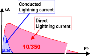
2. Lightning current comprise
 |
8/20 wave: current waveform which passed through equipment when subjected to an over-voltage (low energy) 10/350 wave: current waveform which passes through equipment when subjected to an over-voltage due to direct lightning strike. |
3. Impulse withstand voltage of equipment
Equipment tolerance levels are classified according to 4 categories as the following table,
| Categories | Un (230/400V | Examples |
| Ⅰ | 1500V | equipment containing particular sensitive electronic circuits computer workstations,
computers, TV, HiFi Video, Alarms, etc; Household appliances with electronic programmers, etc |
| Ⅱ | 2500V | Domestic electrical equipment with mechanical programmers, portable tools, etc. |
| Ⅲ | 4000V | Distribution panels, switchgear, etc. |
| Ⅳ | 6000V | Equipment for industrial use and equipment such as fixed motors permanently connected to the fixed installation, Electrical meters, principle over-current protection equipment, remote measurement devices, etc. |
The protection level Up is chosen according to the equipment to be protected.
3. SPD working principle
In normal situation, the impedance of SPD is very high and no current follows thought it, but when the power lines are stricken by lightning or produced high transient voltage by induction or other reasons, SPD will immediately response within nanoseconds and cause the surge current to flow down to the earth, thus the equipments connected to power network are effectively protected.

In application, the reason cause the SPD fire or burst arlong time over-voltage of the network: high voltage applied in the two terminals of SPD, and cause high temperature of SPD inside.
Fault of MOV: MOV fault or short circuit because of over-voltage strike, cause the network short circuit to earth.
Thermal cutoff member is designed to disconnect the overloaded SPD in time to avoid a fire hazard.
SPD thermal cutoff disconnector Operation Principle
When the MOV malfunction, there is also current flow through the MOV and generate heat energy.
When the temperature increase to certain point (140℃), the melt point will be melted down, and there is no current flow through MOV, and then the separating lever props the cooper flake up, then the indicative window will turn green to red, and there is no current flow through the MOV. So, there won’t generate heat energy, and prevent the device from fire.